Spatial Dimensions is a UK measured building survey and geospatial company, founded in 2012, producing CAD drawings in-house at permanent offices in London, Sevenoaks and Nottingham, from survey data captured anywhere in the UK.
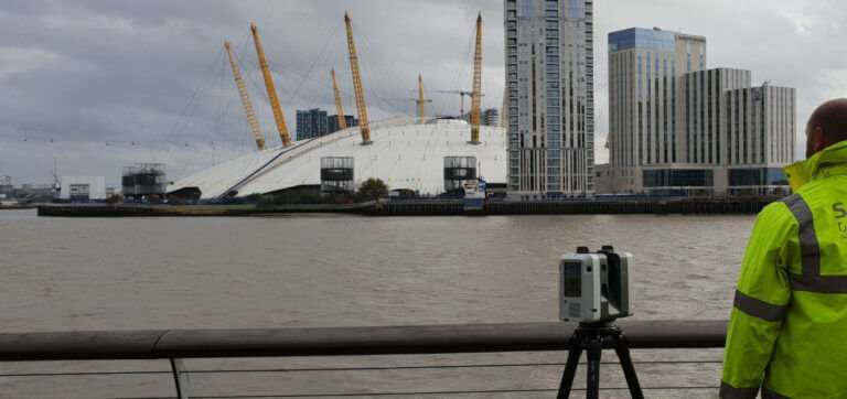
CAD drawing production is the drafting arm of our survey services. Our surveyors capture the building or site with Leica BLK, RTC360 and P-series laser scanners; our own CAD technicians register, check and draft that data into finished drawings. Everything is drafted in-house, never outsourced.
In short: Spatial Dimensions produces highly accurate plan, elevation and section drawings — floor plans, loft plans, roof plans, elevations, sections and reflected ceiling plans — drawn from laser scan data at LOD 2, LOD 3 or LOD 4, delivered in .DWG, .DXF and PDF, and checked under ISO 9001:2015 before issue. Packages start at £250.
or call 01732 458799
What are CAD drawings?
CAD stands for computer-aided design — producing drawings digitally in industry-standard software. In surveying, CAD drawings are the standard way to record an existing building or site so architects, planners and contractors can design against what is actually there.
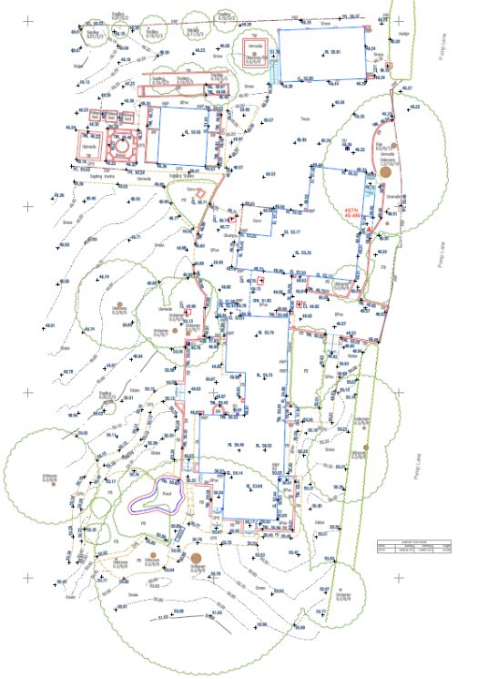
Spatial Dimensions drafts CAD drawings from point cloud data captured by our own laser scanning surveys, measured building surveys and topographical surveys, and from client-supplied third-party survey data. Drawings are produced in accordance with British Standards and are suitable for architectural design and planning applications.
What drawings can Spatial Dimensions produce?
Spatial Dimensions produces six drawing types from survey data, each to a level of detail agreed in writing before drafting starts.
- Floor plans — structural walls, columns, stairs, openings and floor levels at every level of detail; partitions, fixed furniture and services join as the LOD rises.
- Loft plans — roof structure, ceiling falls, ridge lines and skylights, down to individual rafters, struts and braces at LOD 4.
- Roof plans — parapets, chimneys, ridge and eave lines with fall directions, skylights and dormers.
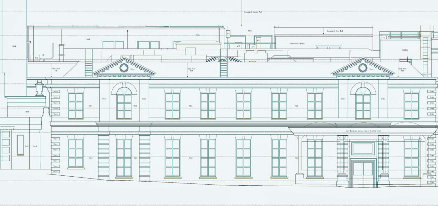
- Internal and external elevations — structural building lines and openings, with fenestration from LOD 3 and brick-by-brick detail, including structural defects, at LOD 4.
- Sections — a section is a vertical cut through the building, showing how spaces and levels relate. Where the cut line falls decides what the section shows, so we agree cut positions with you before drafting. Standard cut sections are presented at LOD 3 on the cut line; where detail beyond the cut line is needed, elevated sections are drawn at LOD 2, 3 or 4.
- Reflected ceiling plans — plans of the ceiling, drawn as if reflected in a mirror on the floor so the orientation matches the floor plan.
What level of detail (LOD) do I need?
The level of detail decides what appears on the drawing, how accurately, and what it costs, so Spatial Dimensions defines it in writing on every quote.
Swipe the table sideways to see all the columns.
| LOD 2 | LOD 3 | LOD 4 | |
|---|---|---|---|
| Drawing scale | 1:100 | 1:50 | 1:20 |
| Linear tolerance | ±20 mm | ±10 mm | ±5 mm |
| Smallest feature drawn | 100 mm | 50 mm | 10 mm |
| Typically used for | Planning applications, rights to light | Architectural design | Heritage records, detailed inspection |
Summarised examples by drawing type:
Swipe the table sideways to see all the columns.
| Drawing type | At every level | Added at LOD 3 | Added at LOD 4 |
|---|---|---|---|
| Floor plans | Structural walls, stairs, openings, floor levels | Partitions, fixed and sanitary furniture, window fenestration, pipes 75 mm and over | Radiators, sockets, skirting boards, pipes under 75 mm shown individually |
| Loft plans | Structure, ceiling falls, ridge lines, skylights | Tanks, major plant, ridge boards, purlins | Individual rafters, struts and braces |
| Roof plans | Parapets, chimneys, ridge and eave lines with falls | Coping stones, fixed ladders, major plant | Drainage runs, cable trays, lightning tape, aerials |
| Elevations | Structural building lines, openings, roofs, parapets | Window and door fenestration, signage, pipes 50 mm and over | Brick and stone detail, detailed railings, structural defects |
| Reflected ceiling plans | Structure above door head level, skylights, hatches | Cornicing over 50 mm, light fittings, smoke detectors | Individual ceiling tiles, fine mouldings |
The full inclusion schedules for every drawing type are set out in the Spatial Dimensions 2D Level of Detail guide, free to download from our guides page, and summarised on our measured building surveys page. If you are not sure which level you need, tell us what the drawings are for and we will tell you honestly which fits.
What formats do you deliver CAD drawings in?
Swipe the table sideways to see all the columns.
| Deliverable | Format | Notes |
|---|---|---|
| Native CAD drawings | .DWG, .DXF | 2D linework, or 3D linework with 3D points on request |
| PDF plan sets | For planning submissions and non-technical stakeholders | |
| Paper copies | Printed sheets | On request |
Drawings follow the standardised line types and layering system of the Spatial Dimensions CAD library, or your own office CAD standards and layers — tell us at quotation stage.
If your project also needs a 3D Revit model, 2D plans, elevations and sections can be extracted from the model as an extra. One caveat: Revit-extracted 2D sheets carry no level or height information unless enhanced 2D drawings are specified — if you need levels on them, say so when we quote.
How are Spatial Dimensions CAD drawings checked?
Every drawing passes a multi-stage check under our ISO 9001:2015 certified quality management system: processing is verified, drafting is checked, and an independent senior reviewer — never the person who captured or drafted the data — signs it off.
Because drafting stays in-house, every drawing is covered by our £10 million professional indemnity insurance. Where something could not be surveyed, the drawing says so, with the limitation documented and explained, not hidden behind a generic disclaimer.
Do I need a CAD drawing service or a measured building survey?
Many clients come to Spatial Dimensions saying “we need drawings”. If no reliable survey data exists yet, the honest answer is a measured building survey with the CAD drawing schedule agreed up front — the survey captures the building; the CAD team drafts it.
If you already hold survey data, we draft straight from it — Spatial Dimensions captures point clouds through our own point cloud surveys, and drafts from client-supplied clouds and third-party survey information too.
Design practices also use our CAD team as an outsourced drafting resource — a fully managed external CAD department working to your standards, or overflow capacity when your workload peaks.
How long does CAD drawing production take?
Where site capture is needed, Spatial Dimensions mobilises in an average of 5.3 working days from instruction, anywhere in the UK. Every quote states site time and drafting time separately, and multiple technicians often work a single project to speed the turnaround.
Drafting from a supplied point cloud needs no site visit; work starts once we have checked the data. Drafting time depends on the size of the building, the drawing schedule and the level of detail — LOD 4 takes materially longer than LOD 2.
Who commissions CAD drawings from Spatial Dimensions?
Around 40% of our work comes from architects and space planners, 30% from property consultants, project managers, quantity surveyors and engineers, 25% from main contractors and site teams, and the rest from private clients.
- Architects — existing-conditions sets for RIBA Stages 2 to 4
- Planners — accurate existing drawings for planning submissions
- Contractors — as-built records and construction drawings
- Consultants — plans supporting area referencing and due diligence
- Estate agents — accurate floor plans for marketing
- Lawyers and engineers — plans supporting lease, Land Registry and engineering work
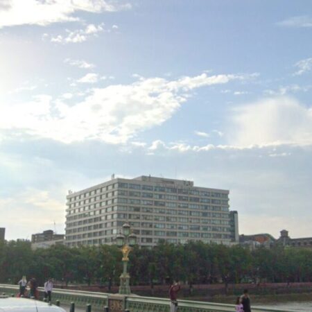
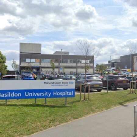
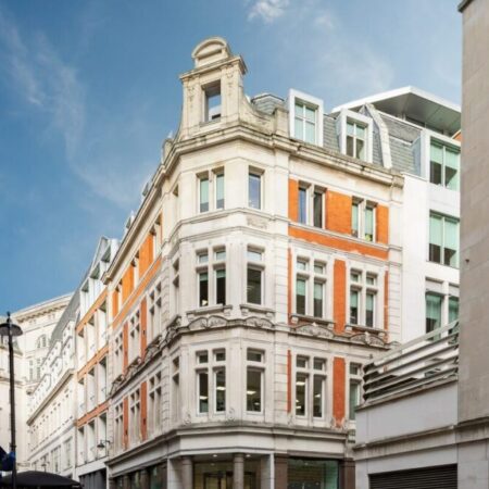
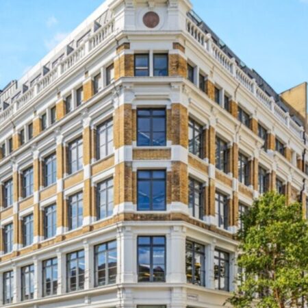
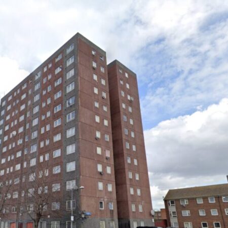
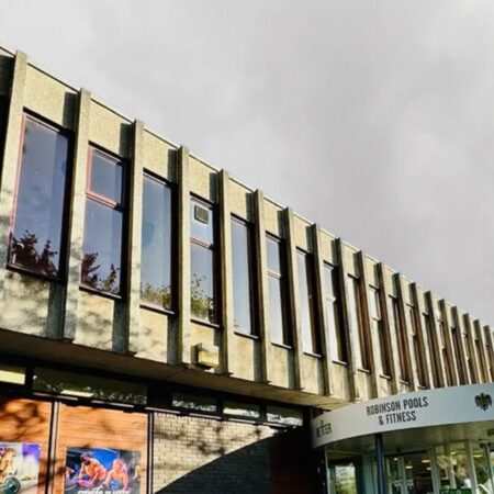
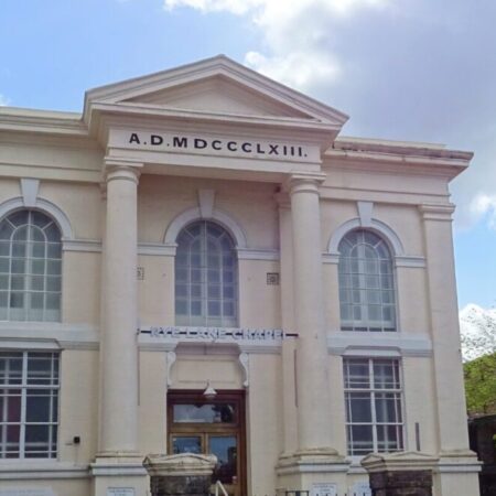
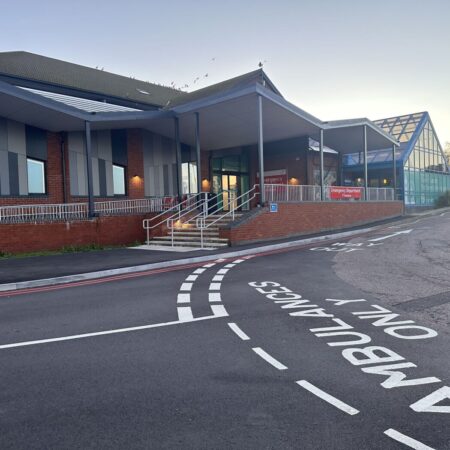
CAD projects include St Thomas’ Hospital and Basildon University Hospital (healthcare), 1 Vine Street and 77 Farringdon Road (offices), Barking & Dagenham (residential), Lincoln City FC, Robinson Pools & Fitness (sports) and Rye Lane Chapel (heritage).
How much do CAD drawings cost?
A CAD drawing package from Spatial Dimensions starts at £250. Most CAD drawing packages fall between £500 and £7,500, depending on the size of the building and which drawings are on the schedule.
The price of a CAD drawing package depends on five things: the size of the building or site, which drawing types are on the schedule, the level of detail, whether we are capturing the data or drafting from yours, and the formats you need.
Spatial Dimensions quotes a fixed price against a written specification — the drawing schedule, LOD, tolerances and formats are all stated before you commit.
For a fixed price, send us the building address, what the drawings are for and the drawing schedule if you have one. We will come back with a written quote within 24 hours. All prices exclude VAT.
or call 01732 458799.
Frequently asked questions
Floor plans, loft plans, roof plans, internal and external elevations, cut and elevated sections, and reflected ceiling plans — from our own survey data or yours, at LOD 2, 3 or 4, in .DWG, .DXF and PDF.
A reflected ceiling plan shows the ceiling of a space as if you were looking down at a mirror on the floor reflecting it, so the layout keeps the same orientation as the floor plan. It records structure above door head level, with light fittings, smoke detectors and cornicing from LOD 3.
Both, usually. .DWG (or .DXF) is the editable CAD file your design team works in; PDF plan sets suit planning portals and non-technical stakeholders. Spatial Dimensions supplies both, and paper copies on request.
Tell us what the drawings are for and we will tell you. As a rule of thumb: planning applications sit at LOD 2, architectural design at LOD 3, and heritage recording or detailed inspection at LOD 4. Specifying more detail than the project needs is the most common way of overspending.
Yes, provided the cloud has the coverage and registration quality your level of detail needs. Send it over and Spatial Dimensions will tell you plainly whether it is good enough before you commit.
Yes. Floor plans carry general floor levels at every LOD, and from LOD 3 we add levels to window cills and heads, door heads, beams and ceilings. The exception is 2D sheets extracted from a Revit model, which carry no level or height information unless enhanced 2D drawings are specified.
Through a multi-stage check under our ISO 9001:2015 quality management system — processing verified, drafting checked, then an independent senior review. The person who drafts a drawing never signs it off, and all checking happens in-house.
Request a CAD drawing quote
Send us the building address, what the drawings are for, and whether we are capturing the data or drafting from yours; Spatial Dimensions will reply with a written, fixed-price quote within 24 hours.
Email: website@spatial-dimensions.co.uk
Phone: 01732 458799
Offices: London · Sevenoaks · Nottingham · working nationwide
Related services
- Measured building surveys — the survey behind most drawing packages
- Laser scanning surveys — how the data is captured
- Point cloud surveys — the measured dataset we draft from
- 3D models — Revit models, with 2D sheets extractable as an extra
- Topographical surveys — site drawings and levels